How To Add Bluetooth To IoT Devices Using HC-06 Module

Bluetooth DIY IoT maker projects
0
(0)

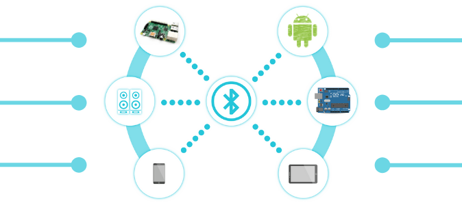
In this practical step-by-step guide I give a detailed explanation of how to build a Bluetooth module and how you can use Bluetooth in your IoT devices at home.

Some IoT devices will already have Bluetooth capabilities build-in to the board, however some do not.

This guide will help you add Bluetooth to those boards that do not have this built-in Bluetooth feature.


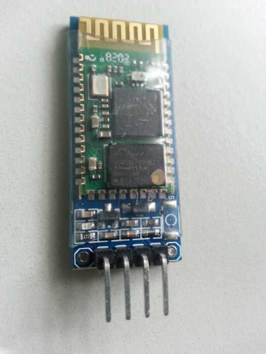
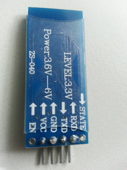
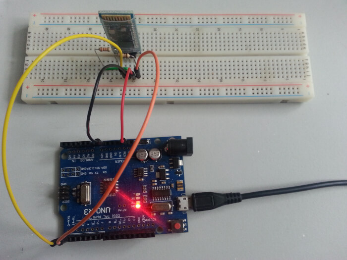
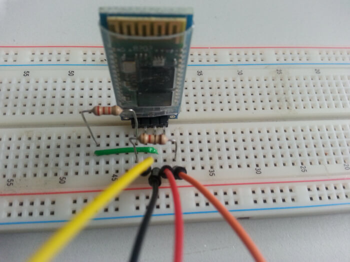
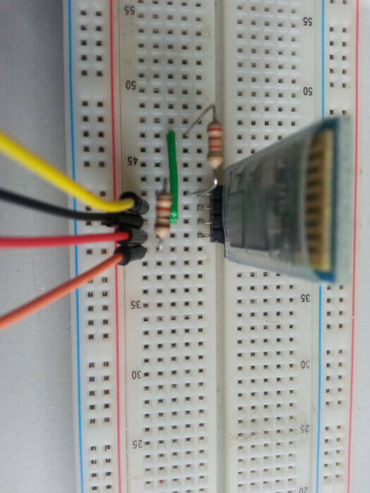
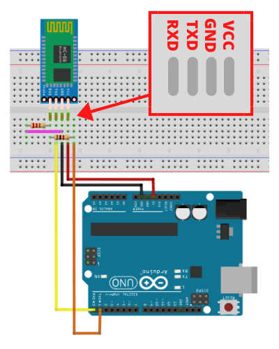
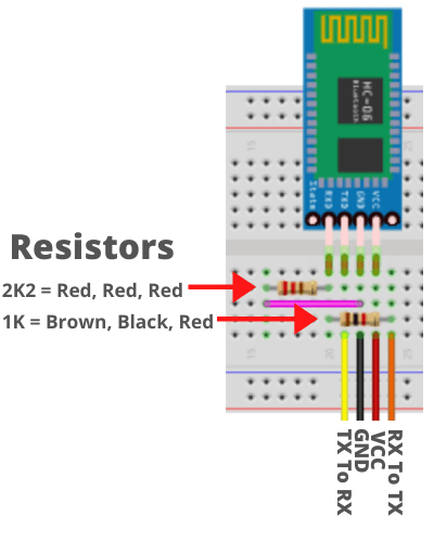
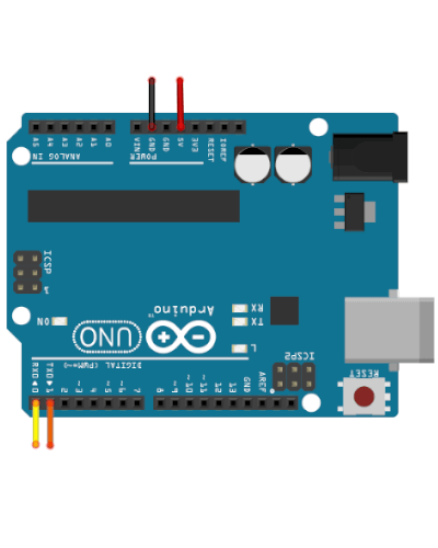
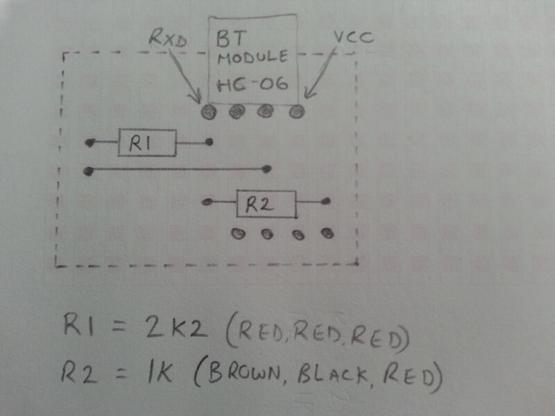
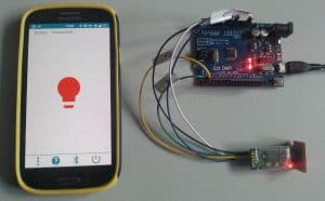
I will also take you through a demonstration of how to physically setup the Bluetooth module for the first time by using the Arduino Uno microcontroller board. (The Arduino Uno does not have built-in Bluetooth capabilities).

By following along with this guide I assume that you are an absolute beginner who is keen the learn about DIY IoT projects that use the Bluetooth communication standard.


If you’re unsure about what an Arduino actually is then now would be a great time learn more about it before progressing with this guide. To get up to speed with Arduino you can follow my beginner’s guide here.


This Bluetooth guide goes hand-in-hand with my other post on how to control an Arduino LED via Android using Bluetooth communication. However I would recommend following this guide first as you will need to build the Bluetooth module first before a project can be built.


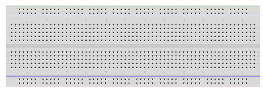
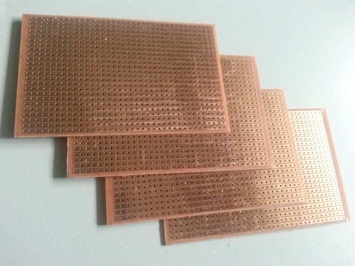
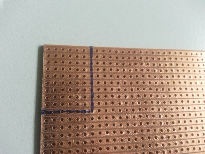
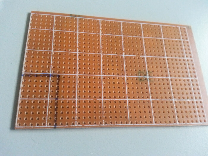
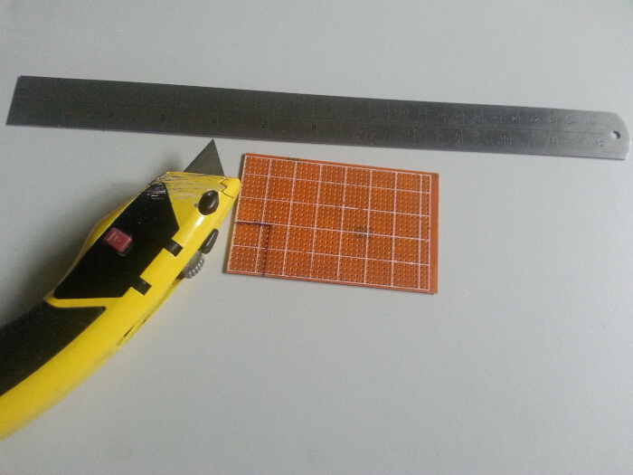
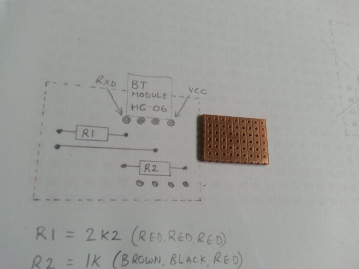
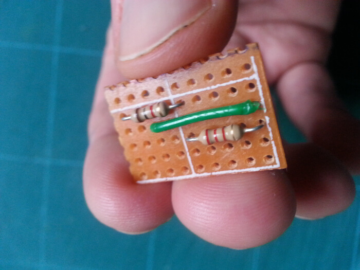
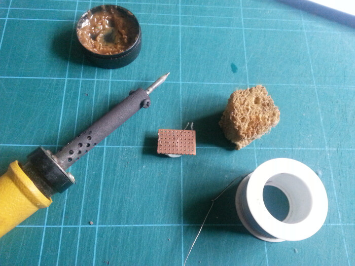
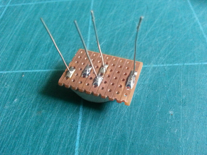
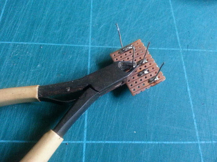
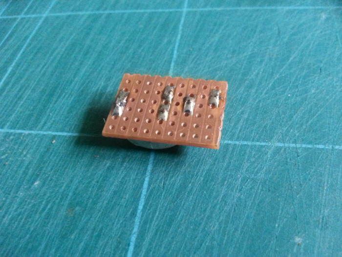
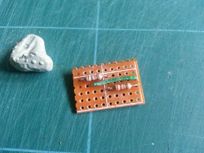
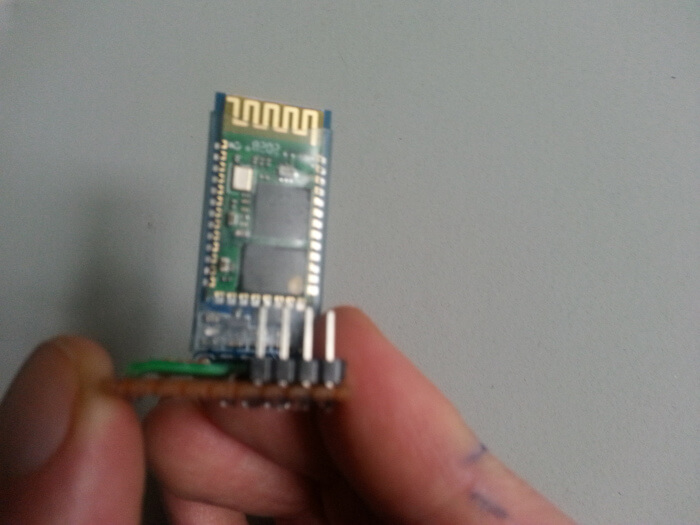
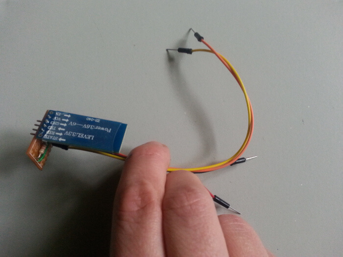
Whether your interested in building a permanent project using a soldering iron or by simply creating a quick and solderless prototype I will cover both of these methods below.

Contents

Tools & Equipment You Will Need

If you currently have plans to build many IoT projects then acquiring the basic tools and equipment first is a good place to start. My basic hand tools and equipment for electronics projects post will cover everything you need to get started.


The following components will be used in this guide and link to Amazon.com products where possible:


1000 ohm (1k) fixed resistor

2200 ohm (2k2) fixed resistor

Single core hookup wire

Stripboard or breadboard (Depending on approach)

Header Pins For Stripboard Approach (Optional but recommended)

Which Bluetooth Module Do I Use?

Currently there are three popular and competing Bluetooth modules that can be used for DIY IoT projects available on the market today.

Of course there will be others but these three modules are what you will see more often than not.

These are:

  • HC-05
  • HC-06 Without Supporting Board
  • HC-06 With Supporting Board
Links to these products on Amazon can be found in the following images and can be purchased for less that $10 each:

HC-05

HC-06 Without Supporting Board

HC-06 WIth Supporting Board

To follow along with this guide you will need the third option here which is the HC-06 WITH Supporting Board.

HC-06 Bluetooth Module With Supporting Board

The following photos show the front and back of the HC-06 module in a little more detail:

HC-06 Bluetooth Module

Option 1: Prototype IoT Bluetooth Project With Breadboard

Whether you’re building simple projects at home or something a little more complex, you are going to need breadboard. 

These can be found in many different shapes, sizes and colors.. however they all work the same way.

Here is a link to a full-sized breadboard on Amazon.com.

How Does Breadboard Work?

The following image shows a full-sized breadboard used for prototyping electronic circuits. White is the most common color:

Original Breadboard
Breadboard

As you can see, this board is full of holes and it’s important to understand which holes are connected together.

The following image shows these connections:

Pin Connections

The following image shows the positive rails shown in red and the negative rails are shown in black.

Of course you can always connect these tracks to anything you please but are usually marked out on breadboard to help guide you: 

Breadboard Highlighting Power Rails
Highlighting Power Rails

Real-World Bluetooth Module To Arduino Uno Layout

Now that we’re familiar with using the breadboard it’s time to populate the board with our components and connections.

The following photos show how I connected the HC-06 module to it’s supporting components such as resistors and an Arduino Uno:

Bluetooth Module To Arduino Uno Layout Diagram

The following three diagrams show in detail and more clearly how the connections are made in the photos above:

Option 2: Solder Bluetooth Module With Supporting Components To Stripboard

Finished Product

The photo above shows my completed project soldered to stripboard.

In this next section I will guide you through the process of how you can build this project yourself at home.

Stripboard / Veroboard

Using breadboard is a great way to test a circuit before building a more permanent project.

But once you’re confident that everything seems to work as expected then the next logical approach is to solder everything together.

To follow along with this next phase then you’re going to need some stripboard.

Here is a link to stripboard found on Amazon.com and the following photos show what typical stripboard looks like:


Stripboard/veroboard ships in various shapes and sizes and we will only require a small amount for this project.

We will need to cut some of this down to the size we need.

Design The Circuit Layout

You can design your layout any way you like but the above photo shows my design. Please feel free to follow along with my design or create your own.

Mark Out The Cutting Lines On Stripboard

The photo (above left) shows me marking out the correct size for the project. I marked this out on the copper strip side of the board first to make sure the strips we in the correct orientation.

However I recommend cutting the stripboard from the reverse side of the copper tracks. This reduces the chance of accidentally removing the copper.

For this reason I also marked out the line on the reverse side of the board.

Using a steel ruler, a craft knife and a cutting mat I proceeded to cut the board.

Cut Stripboard/Veroboard

More photos show me cutting the stripboard. I used some heavy duty snips pliers to finish cutting the board.

File And Sand Rough Edges

After the board has been cut, I use a steel file and then some sandpaper to clean the rough edges down.

Clean Copper Tracks

Next it’s time to clean the copper tracks. It’s not recommended to skip this step as it’s important to get clean solder joints to the copper.

Using an eraser-type tool specifically designed for electronics is used here. 

Final Check Before Soldering

It’s worth checking one last time that the stripboard matches the design before any soldering takes place.

Insert Low-Profile Components First

If you’re new to soldering electronics then the number one piece of advice I can give you right now is to solder the low-profile components first.

This makes it easier to flip the board upside-down to perform the actual soldering.

The photos above show me placing the first components in to place before soldering. This is the two fixed resistors and the link.

Hold Components In Place Ready To Solder

Now we get to do some soldering!

Pressing down some Blu Tack to the components will stop them from falling out. I have a hot soldering iron, a wet sponge, flux and solder ready to go!

Add Solder Flux To Joints

By using the end of my round-nose pliers I can apply some solder flux to the joints before soldering.

This helps the solder bond to the metal.

Solder And Trim Leads

After the first session of soldering is done I can then snip away the leads and remove the Blu Tack.

Soldering Male Jumper Leads (Option 1)

It’s possible to solder the jumper wires directly to the stripboard. If this is the approach you take here then all I can recommend is to scrape the wire pins with a craft knife first. This will help the solder bond to it.

However, when I was building this project I found that the wires were not bonding good at all.

I later decided to remove these wires and solder a 4 pin header instead as you can see from the photos below.

Solder Header Pins (Option 2)

The header pins made a much better connection than soldering the wires on directly.

These header pins usually ship in a long length as you can see from the photo above and to the left and are easily cut to the length of your choice by using snips/pliers.

Solder HC-06 Bluetooth Module & Finishing Up

The final piece to the puzzle so to speak was soldering the HC-06 module its self to the board and trim its wires underneath.

And that’s it!

Once I was happy with all of the connections I performed a quick functionality test which I will explain in the next section.

Build A Beginner's IoT Maker Project

Once you have completed your shiny new Bluetooth module it’s time to test it.

By connecting the module to an Arduino Uno we can use an Android device to blink on/off the on-board LED via an app.

This post “Bluetooth Arduino LED To Android With FREE Kodular App” will show you how to complete this beginner’s project.

Conclusion

In this guide I explained how to use Bluetooth in IoT devices & DIY home maker projects by connecting up a HC-06 Bluetooth module.

I covered the simple breadboard layout for basic testing and then a step-by-step guide on how to solder the project together using stripboard.

This module can be used in almost any open-source hardware development boards such as the Arduino family plus many more!

If you’re new to electronics in general then I hope this project has boosted your skill level up a notch ready for you to tackle more complex projects in the future.

Thanks

installtekz icon

Quote Of The Day

installtekz

"When wireless is perfectly applied, the whole earth will be converted into a huge brain..." - Nikola Tesla, 1926

How useful was this post?

Click on a star to rate it!

Average rating 0 / 5. Vote count: 0

No votes so far! Be the first to rate this post.