What Is OSI Model In Simple Words? (4 Step Guide)

OSI and TCPIP model
5
(1)


Transmission Control Protocol / Internet Protocol (TCP/IP) and Open Systems Interconnection (OSI) Reference Models

Don’t get freaked out by the heading above! This is simple stuff 🙂 What is OSI model in simple words?

Let’s find out how our computers work together over the internet!


Have you seen the Wikipedia page on the OSI model?!

You need a computer science degree just to understand it!

Here I will explain it in a more human-readable format 🙂


I will try to keep this post short and sweet. But if you’re learning this for the first time then this will most likely take you weeks.. months.. or even years to memorise the OSI and TCP/IP models.

(Hopefully you can remember the order of the layers quicker than I did).


I was unsure whether to create separate post’s for the OSI model and the TCP/IP model, but then I didn’t know where I would explain how these two models map together, and so I am going to explain it all right here.


These models are part of understanding TCP/IP and so if you haven’t already checked out my TCP/IP post then you can read up on it here.

This will give you a more in-depth explanation of what exactly TCP/IP actually is.

After reading through this post, I am hoping you will have an understanding of what these models are and why we would use them in computer networks.


I’ve kept coming back to this subject over many years because I haven’t fully remembered everything to it as there’s so much going on here.


But here you will understand just how data is sent across a network, where certain protocols operate and how we would troubleshoot networking problems.

progress 20

Contents

1. What is the OSI model?

Okay, this thing doesn’t actually exist anywhere except on paper (so to speak). 

This is all theory and some of it DOES require some memorisation. Here is an image of what the OSI model looks like:

what is osi model in simple words
OSI Model

Layers

The first thing I want to talk about is layers. This model is made up of 7 of them. We need to memorise what order the’re in.


You can either memorise them from top to bottom, or from bottom to top.

We can use the acronym: PDNTSPA for remembering the model from bottom to top, or the acronym: APSTNDP to remember the order of the model from top to bottom.

I’m sure we’ve all used this method before at some point in our lives where we would use a completely random, made-up sentence to remember something. This is how I remember the order of the layers.
 
Me personally, I use the ‘bottom to top’ method. This is slightly embarrassing, but the sentence that I use is this: ‘People Don’t Never Tell Strangers Personal Accounts.’
 
This has stuck with me and this is how I remember it but go crazy and make up your own if you wish. Anyway that gets you to remember the order is all that matters here.
 

Order of layers

Next we need to remember that the bottom layer is Layer 1, and the top layer is Layer 7.

  • Layer 7: The Application layer
  • Layer 6: The Presentation layer
  • Layer 5: The Session layer
  • Layer 4: The Transport layer
  • Layer 3: The Network layer
  • Layer 2: The Data Link layer
  • Layer 1: The Physical layer

Now imagine you are sat at your computer (if you’re not already!) and your computer is made up of these 7 layers.

You would be viewing this website in the web browser. You probably have a desktop environment with your windows open.

This is the Application layer. This is the layer that you interact with the computer at.

The Presentation layer deals with, well, presentation. This is things like encryption.

The Physical layer is where the Ethernet cable is sending and receiving your data out into the internet.
 
I will go into more depth on the layers further down this post.

Using the term: Data

It’s important to know that the term “DATA” is only used at the top 3 of these layers. The list below shows what we actually call this and at what layer:
 
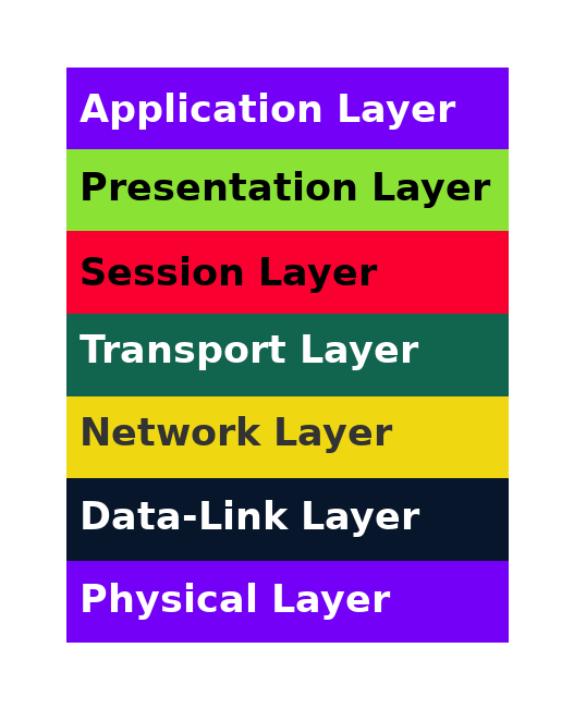
Layer 7 / Application = DATA
Layer 6 / Presentation = DATA
Layer 5 / Session = DATA
Layer 4 / Transport = SEGMENTS
Layer 3 / Network = PACKETS
Layer 2 / Data Link = FRAMES
Layer 1 / Physical = BITS
 
Try to memorise the phrase “Segments, Packets, Frames, Bits”.
 
The reason why we use different terms for our data in the Transport layer, Network layer, Data-Link layer and Physical layer is because at these layers, our data is being broken down and ready to be sent across the network to another host.

Interchangeable names

If we take layer 7 for an example here, we can refer to this as Layer 7, The Application Layer, or simply L7. These three terms are describing the same thing. 

If you’re working in a networking environment and a fellow employee mentions PACKETS then you should immediately know that he/she is talking about the Network layer.
 
Or maybe he/she says something like “We have a Layer 3 issue” then you should immediately know that they are referring to the Network layer.
 
This may take a while for you to remember but if you go through everything so far that I’ve talked about and familiarise yourself with all the different terms, then it all starts to sink in.
progress 40

2. What Is The TCP/IP Model?

The TCP/IP referencing model is smaller than the OSI model but works the same way, except it’s not as detailed.

what is osi model in simple words
TCP/IP Model

As you can see from the diagram above, the TCP/IP model is made up of only four layers. The Application layer, Transport layer, Internet layer and the Network Access layer.

Sometimes you may see the “Internet layer” referred to as the “Internetwork Layer” but these are essentially the same thing.

progress 60

3. Mapping The Two Models Together

As we can see from the diagram below, the TCP/IP model’s “Application Layer” is made up of the OSI model’s “Application Layer”, “Presentation Layer” AND the “Session Layer”.

Also notice the TCP/IP model’s “Network Access Layer” is made up of the OSI model’s “Data-Link Layer” and “Physical Layer”.


The TCP/IP model’s “Transport Layer” is identical to that of the OSI model’s “Transport Layer”.

However, the TCP/IP model has a layer called the “Internet Layer”. This is mapped to the OSI model’s “Network Layer”.

what is osi model in simple words

Don’t get these two models mixed up with each other.


If you’re asked a question in an exam about an OSI model’s layer then you don’t want to be giving an answer that’s related to the TCP/IP model!


Instant point removal right there! 😛

progress 80

4. Whats Happening At The Layers?

In the real world of IT we will be required to use either the TCP/IP model or the OSI model for troubleshooting.

I personally use the TCP/IP model as it’s more detailed and I always hear other Network Admins use this model too.

But the decision is ultimately yours. However, for an exam, you will need to know them both.


Here I will give a brief explanation of what’s going on at each layer, however I plan to create separate, more detailed posts on this site about everything I skim over on, in this post.

From here on in, I will talk about the OSI model. But the same concepts apply for the TCP/IP model too.

Most of the time as a Network Admin we will be mainly working at the bottom 3 layers (Physical, Data-Link and Network Layers).

There are MANY protocols and network devices that operate at different layers of the OSI model.

(A protocol is a software program. It’s a set of rules that run on two separate devices and allows them to communicate over a network).

Two of the most common network devices are switches and routers.


A network switch device operates at the Data-Link Layer (Layer 2) and deals with MAC addressing and Frame data.

If you would like to learn more about MAC addressing then why not check out my other post on ‘What is a MAC address and why do we need it?‘.

A router is a layer 3 device, and so it operates at the Network layer of the OSI model. The router and the layer as a whole deals with IP addressing.


When dealing with routers, we are dealing with packet data don’t forget. A router works at 1 level above network switches.


There are also layer 3 switch devices out in the wild. These are simply routers and switches combined into a single device.

Application Layer

Authentication happens at the Application layer (Layer 7). The email protocols POP3 and SMTP also run on the Application layer.


As does Telnet, FTP, SNMP and HTTP.


These are not exhaustive as many more protocols operate on this Layer.


If a user interacts with a software program, then that particular program will be running in the Application layer.

Presentation Layer

The Presentation Layer focuses on exactly that.. the presentation of the data.


Have you ever tried to open a Word document with a plain text editor? 


If so, you will notice that the information in the document is unreadable. This is a presentation layer issue.


File extension types work here such as “jpeg” and “png” for example.

Session Layer

At the session layer, a two-way communication link is established here between two hosts over a network.

Some sessions last longer than others.

Not only does this layer establish the connection but it also maintains that connection and then it tears down the connection once a particular session is over.


You could say that this layer is the manager of the communications link between two hosts.

Transport Layer

The Transport layer is where we deal with segments.

The Transport layer’s job is to get the data (segments) to it’s remote destination host, get there free from errors, and get there in the correct order.
 

TCP and UDP are two of THE biggest protocols that you will need to know in computer networking that use the TCP/IP protocol stack. TCP and UDP are the two protocols that operate at this layer.


These run at layer 4, the Transport Layer of the OSI model and also the Transport Layer of the TCP/IP model.


When ever anyone talks about segments, just remember that they’re immediately talking about the Transport layer and the TCP and UDP protocols.

Network Layer

This is layer 3 of the OSI model. As described above, routers operate at this level and sometimes this layer is often called ‘the routing layer’.


As a Network Admin, you’re likely to spend a lot of your time working at this layer.


IP (Internet Protocol) operates at this layer and so, anything that deals with IP addressing will be running at the Network Layer.


You could also hear the term “Routing Address” or “Layer 3 Address” and these would simply be referring to the IP Address.


This layer needs to know the answer to the following two questions:

a) What routing paths exist between me and the destination host

b) What is the most optimal path to take to get there.


Usually the quickest and most direct route is not always the most optimal path to take.

There could be bottle-necks in the network for example which cause bandwidth to be significantly reduced.

And so the Network layer will decide which path it will take.

Data-Link Layer

Network switches and Bridge devices operate here at layer 2, the Data-link layer. Older modems and DSL modems operate here too.

As does the Ethernet protocol, High Data Link Control (HDLC), Point-to-Point protocol (PPP) and Frame Relay.


I will cover these protocols in depth in another post and link them in here when complete.

Errors can be detected here at the Data-Link layer by means of a Frame Check Sequence, however there are no error recovery at this layer.


Again I will mention here that I have another post ‘What is a MAC address and why do we need it?‘ as this is where the MAC Address operates.


It’s important to note here that the physical address is here. But NOT the physical layer address. Physical address is the MAC (Media Access Control).

Physical Layer

The Physical layer is where our data (bits) are sent across a wire (or wireless) over the network.
Bits are sent as Binary Digits 1 and 0 which is represented from distinctive voltage’s.
 
If you’re interested in how binary is converted to other numbering systems then check out my post on .
The Physical layer is your computer hardware which includes the cables, connectors etc.

When you’re tinkering away on your computer and you’re about to send a file to someone over the internet for example, the data will work it’s way down the OSI model (and TCP/IP model) then out into the internet.

When the user receives your file, his/her computer will reconstruct that file by moving UP the OSI model.

As you send your file down the OSI model, each layer adds it’s own header to the file.


At the receiving end then, the OSI model will strip away the header information from the file as it works it’s way up the OSI model.

The header information that YOUR Data-Link layer adds for example, the remote OSI model’s Data-Link layer will strip that header information away.


Each layer will add/remove it’s own header information, except for the Physical Layer. This is known as “Same-Layer Interaction”.

Don’t get this confused with “Adjacent layer interaction”.

This is the term that refers to OSI model layers on the same host that are next to one another. The Application layer is adjacent to the Presentation Layer for example.


The Data-Link Layer will also add a Trailer as well as a header.

The term we use to describe this data which is coupled with specific headers (or control data) is known as a PDU (Protocol Data Unit) and there’s a PDU for each layer.

what is osi model in simple words
progress 100

Conclusion

This is a lot of info to take in all at one go!

What is OSI model in simple words? Hopefully you have a good idea what the OSI model is now. Along with the TCP/IP model and how they map together!


I really hope you’ve managed to get this far and don’t be put off if you don’t understand everything right now.

You will most likely need to return to this post and read it again and again until the pennies drop (so to speak).


I encourage you to do more research on the subject of the TCP/IP and OSI models as you may find that you will learn it better by using multiple sources of training material.

But saying that, I hope I’ve explained everything in a way that’s easy for you to understand.

By understanding these two models we can use a structured approach to troubleshoot ANY TCP/IP network in the world.


What is the first thing we do when our computer isn’t connected to the internet when it should be?

Besides from rage and/or freak out, we check to see if the cables are connected, that they’re connected correctly and that everything is switched on, right?

Well this is troubleshooting at the Physical layer!


If everything checks out OK we then move up the OSI model and begin to troubleshoot at the Data-Link layer.

Can you see now just how these models could help us out in a network environment?

installtekz icon

Quote Of The Day

installtekz

"When wireless is perfectly applied, the whole earth will be converted into a huge brain..." - Nikola Tesla, 1926

How useful was this post?

Click on a star to rate it!

Average rating 5 / 5. Vote count: 1

No votes so far! Be the first to rate this post.