How To Control LCD With Arduino Bluetooth And Android App

Control LCD With Arduino Bluetooth Android
5
(2)

This practical project guide will take you through the steps needed to build a 16×2 LCD (Liquid Crystal Display) module with an Arduino Uno board using a Bluetooth connection to an Android device.


I have also created an Android app for this project which allows you to:

  • Send data from Android over Bluetooth to display on the LCD
  • Send commands from Android over Bluetooth to control the LCD

This app saves time by sending data and commands on-the-fly to the Arduino and omitting the need to flash the Arduino sketch every time a change is made to it.


This project is great for:

  • Beginner’s who want to learn more about how to control a 16×2 LCD
  • Anyone building an LCD project who needs to work out what lines of Arduino code should be executed in any given order
  • Fun!
 
I have also included functionality that will allow you to create your very own LCD characters!
Various common sizes of LCD displays can be used for this project such as the 16×4 and 20×4 but this post will focus on the 16×2 display.
 
These displays can also be used with an I2C adapter to dramatically reduce the amount of connections needed.
 
At the moment this post and the app will not be using the I2C adapter however I hope to include this and the other display sizes in the future.
Arduino LCD Playground App Android

Project Skill Level: Beginner

Electronics
1.3/5
Embedded Programming
1.3/5
16x2 LCD Control
4/5
Bluetooth Networking
1/5

Contents

1. Hardware You Will Need:

Basic Tools And Equipment

My Basic Electronic Tools post covers all of the basic hand tools that you may need to carry out this project and you can get to it by clicking this link.


And if you would like a basic guide on what supporting Arduino components and equipment that you may need then I also have that covered too! You can check that guide out by clicking this link.

Section 10 in the above guide is where you will find the relevant information under the heading: “How to build your own Arduino starter kit”.

For this project you will need a 16×2 LCD display.

These components are cheap to produce and are available almost anywhere online. Usually you can find them with a green or blue backlight and should ship with a 16 pin header.

You may need to solder this header on yourself if you choose to use it or you could solder a female header connector if that suits you best.

As you can see from the images above, I have soldered the header pins on to the front of the module as it gives me easier access for prototyping projects.

If this LCD was destined to be built in to a more permanent project then I would have placed the pins facing out of the back of the module to create a cleaner look.

Here is a link to Amazon.com where you can find one of these 16×2 LCD modules.

You will also need the following: (Amazon.com links supplied below)

  • Arduino Uno or other compatible microcontroller board
  • Jumper wires at various lengths and with various connectors (Male to Male, Male to Female, Female to Female) I recommend the Dupont connectors
  • Potentiometer. Various types, sizes and values will work for this project however I use the 10K Preset Pot here. This is used to adjust the backlight of the LCD module to your preferred contrast for better lighting.
  • Breadboard
You will also need parts for the Bluetooth module which I will explain in the next section.
Original Breadboard

Bluetooth Module And Supporting Components

To follow along with this tutorial you will need to either:

  • Build the Bluetooth module with supporting components such as resistors and jumper/hook-up wire using the solder method
  • Or simply plug all of the components into the breadboard

I have a dedicated wiring guide and how you can build this Bluetooth module here.


In a nutshell then, these are the components needed for the Bluetooth Module if you plan to use the solderless breadboard method:

The following images show one of my HC-06 bluetooth modules in a permanent build by soldering to stripboard:

Other Equipment You Will Need

Other than having all of the needed components, equipment and tools ready for this project you will also need the following:

  • PC or Laptop
  • Android device
  • USB cable to suit Arduino to PC/Laptop connection (Not only will this cable power our project but it is also used to write the Arduino sketch to the Arduino)  

2. Software You Will Need:

The following list of software will be needed for this project:

  1. Arduino IDE
  2. Android App (Arduino LCD Playground)

Arduino IDE

The two options available for using the Arduino IDE are:
 
  • By installing the Arduino IDE executable program. The package type you need will depend on what operating system you have on your computer
  • Or you can use the online IDE known as the Web Editor
 

Both of these options are provided by Arduino.cc here.

(Personally I use the install method on linux).

The Android App

The Android app can be found in section 5 later down in this post.

This Android APK file can be installed directly from this page, from Google Play or the Amazon app store.

3. Flashing The Arduino Sketch

Before we begin to build the electronic circuit it’s a good idea to flash the Arduino sketch into the Arduino Uno first.

However, if you have already built the circuit then there is something that you NEED to do before a successful write will happen..

Make sure that the Bluetooth module is not connected to the Arduino as this may cause problems with the sketch upload. (The TX pin on the Bluetooth module to RX on the Arduino will need disconnecting for the duration of the software write.)

Remove Tx to Rx Pin When Uploading Sketch
Arduino write error
Screenshot Shows Error When Tx to Rx Pin Is Connected
Arduino write error
Screenshot Shows Error Timed Out

If this happens, simply wait for the write process to time out after the 10th attempt then remove the TX-to-RX pin as stated above, then try the write process again.

7 Steps To Flash The Arduino Sketch

By following the steps below we can successfully flash the Arduino:

  1. Connect the USB cable to the Arduino
  2. Connect the other end of the USB cable to the PC/Laptop
  3. Start the Arduino IDE software
  4. Copy and paste the Arduino sketch into the Arduino IDE. The sketch can be found further down this page
  5. At this point you may need to select the USB port in place of the “COM” port and the IDE may warn/guide you on how to change this (Tools>Port)
  6. Click the “Verify” button to check that the code will compile
  7. Click the “Write” button to flash the sketch into the Arduino

Arduino Sketch

Over time I will probably roll out new versions of the Android App. When I do this, I may also need to update the Arduino sketch below too.


For this reason I will provide a compatibility note below. Please check that your Android App version that you have installed is compatible with the Arduino Sketch provided here.


Otherwise your App may not function as intended.

The following screenshot shows the sketch inside the Arduino IDE:

Once you’re happy with the sketch you can then click the ‘Verify’ button to confirm there are no errors in the code:

It’s now time to flash the sketch into the Arduino board by clicking the ‘Upload’ button as indicated below:

That’s the Arduino sketch flashing process complete!

4. Building The Arduino Project

The Circuit Layout

Other than flashing the Arduino sketch to the Arduino we also need to connect up all of the electronics.

The following image shows the wiring diagram of how to connect your project together. Once this is complete we need to power the Arduino with the USB cable to a PC/laptop or you can use another source of power if you wish.

The following images show my final hardware setup without power applied to the Arduino:

So now we have the Arduino sketch written into the Arduino, the electronic circuit is built and the Arduino has power.

Don’t forget to adjust the potentiometer with your fingers/screwdriver to vary the backlight contrast of the LCD.


The next steps will involve:

  1. installing the Android app onto an Android device such as a tablet or phone
  2. Configure the Bluetooth connection on this Android device
  3. And finally use the app to control the LCD

The rest of this post will now take you through these next steps:

5. Download & Install The Android App (Arduino LCD Playground)

The Arduino LCD Playground App utilizes the ‘LiquidCrystal’ library supplied by the Arduino team to provide an interactive learning environment and make prototyping more efficient.

Arduino LCD Playground Android App Icon

I have supplied various methods below in which to install the Android app by either:

  • Scanning the QR code using your Android device. This will prompt you to install the app directly from me
  • Click the “Direct Download APK” button to install the app directly from me 
  • Or click an App Store button to take you to the relevant app store.
 

If you are installing the app directly from me then you may need to change a setting on your android device which allows you to ‘install apps from other sources’.

Install APK On Android (Approx. 6.8MB)

OR

Arduino LCD Playground Android App QR Code

App Screenshots

6. Configure Bluetooth On Android

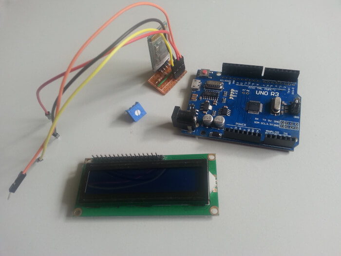
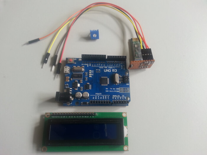
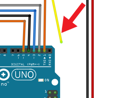
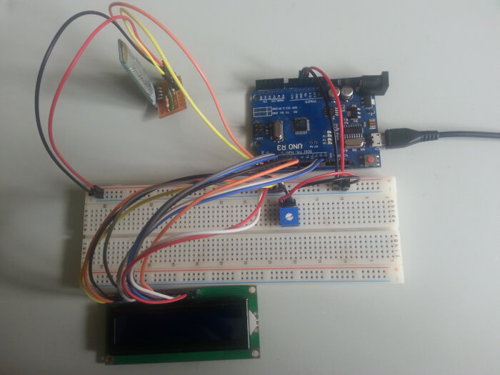
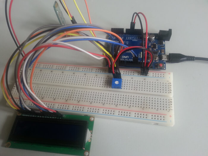
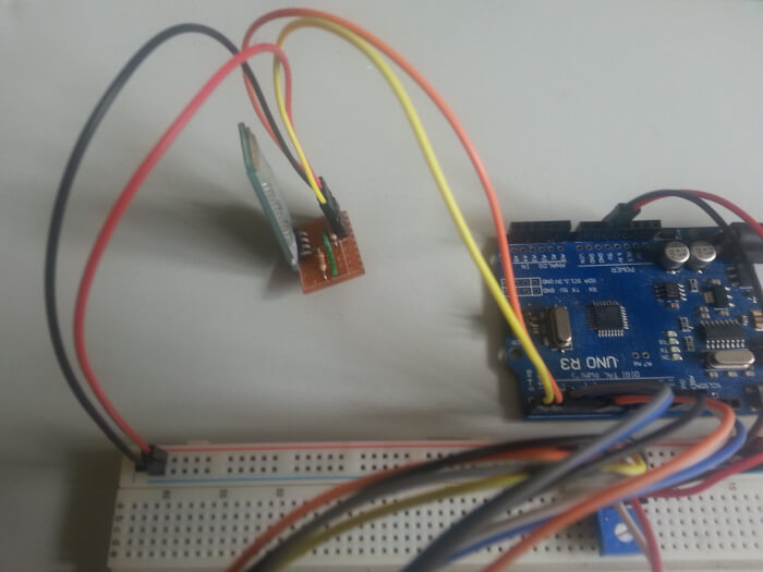
Now we need to provide power to our circuit.

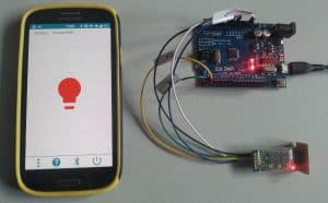
Once the Arduino is switched on, the Bluetooth module should be broadcasting it’s identity and you should see an LED light flashing rapidly.

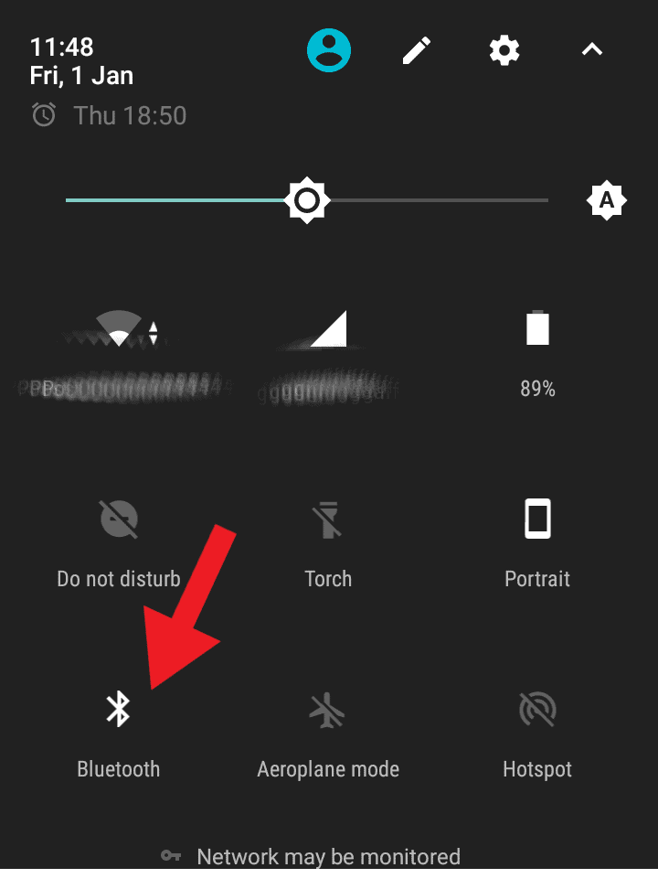
We can see the identity from an Android device when we activate Bluetooth on Android.

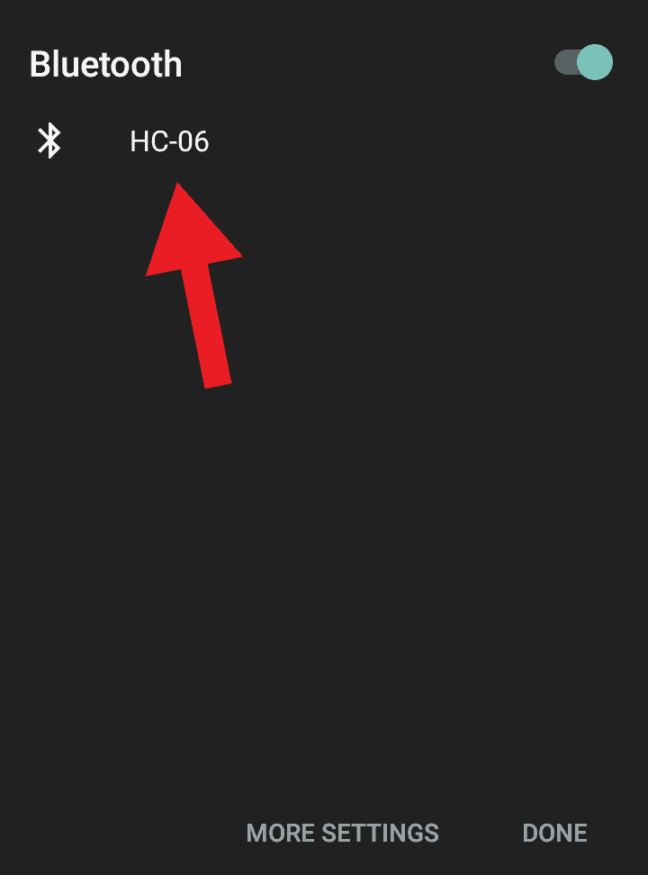
We may need to scan for nearby Bluetooth devices. If you are using the HC-06 Bluetooth module then you should see this displayed on Android as “HC-06“.

If you are prompted for a password then try “1234” to pair Android to the HC-06 Bluetooth module.

The below screenshots show me connecting to Bluetooth from Android:

Turn ON Bluetooth
Connect to bluetooth module

7. How To Use The 'Arduino LCD Playground' App

Connect Via Bluetooth

Once you have successfully paired your Android device to the Bluetooth module it’s now time to open the app.

Click the Bluetooth icon as shown in the image below and select your Bluetooth module which should be displayed in the list as “HC-06” along with it’s MAC address.

Give the connection a few seconds to establish and you should notice the LED light on the HC-06 Bluetooth module flash less rapidly.

It may take more than one attempt to successfully connect.

Connect Bluetooth device

You are now ready to go!

How To Create Your Own LCD Characters

From the home screen there is an icon of a man. Tap this icon to take you to the “Character Creator” screen:

From here you can tap the squares to create your character. Once you are happy with the character you will need to give it a name then hit the “Save” button. Now we can navigate back to the main screen.

Create Custom LCD Character

We can now select our new custom character from the main screen to send as data to display on the LCD display as shown in point 4 in the image below:

Select Custom LCD Character

Conclusion

This instructional guide was intended for anyone wanting to control an LCD module display on an Arduino Uno by using an Android app over Bluetooth communication.

My aim here was to provide you with educational material in the form of an interactive mobile application to learn how to program the LCD.

As this project has no real goal other than to be educational, the app also serves as a playground for sending data and commands to the LCD.

I hope that not only will beginner’s find this project useful but anyone simply wanting a little fun with LCD’s from the comfort of a graphical interface. 

installtekz icon

Quote Of The Day

installtekz

"When wireless is perfectly applied, the whole earth will be converted into a huge brain..." - Nikola Tesla, 1926

ID: 150420211635

How useful was this post?

Click on a star to rate it!

Average rating 5 / 5. Vote count: 2

No votes so far! Be the first to rate this post.